When two worlds meet
How the award-winning Jedlik Ányos Gymnasium project was created
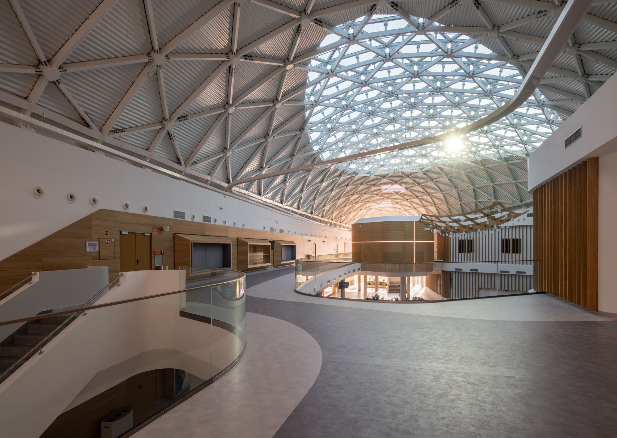
You should always strive for improvement, but in a way that preserves important milestones for future generations while also leaving your own mark. This was our task in Csepel, where we designed the new wing of the existing Jedlik Ányos Gymnasium so that future generations could study in a modern, clean environment that still reflects the spirit of the original building.
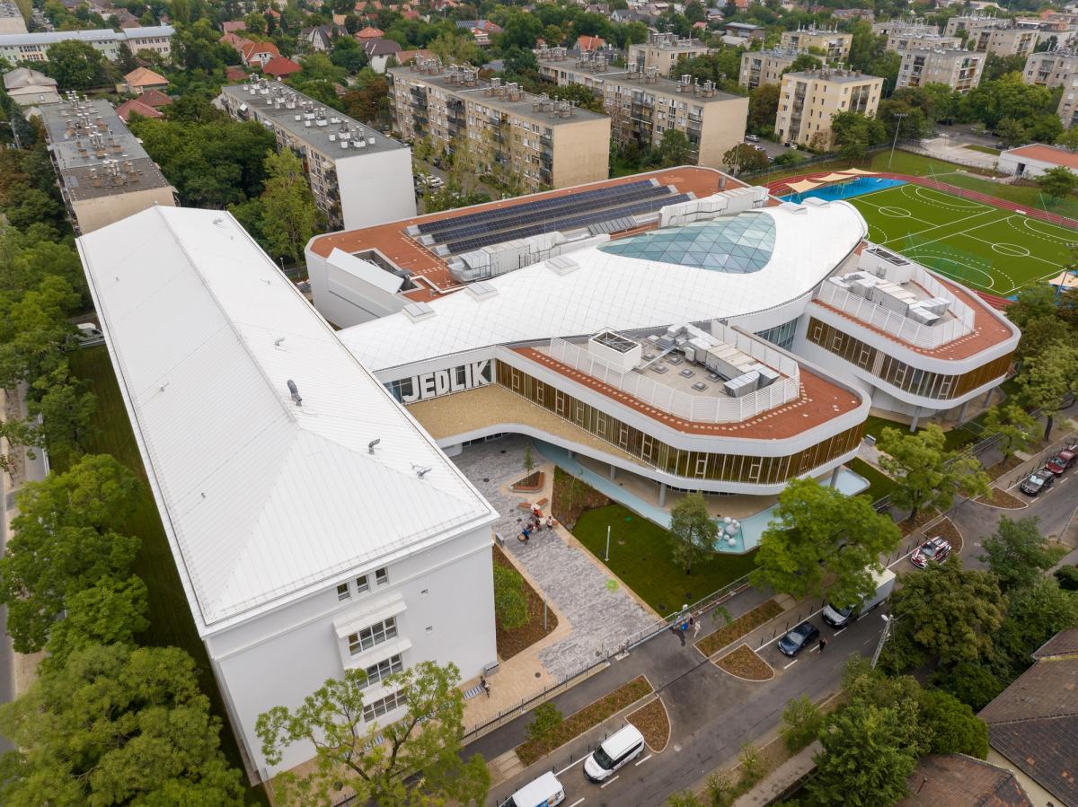
The expansion of the Jedlik Ányos Gymnasium was an outstanding project for us from several perspectives. The educational institution is located in the Csepel district of Budapest, where the development of the existing gymnasium, its expansion by 6,500 m², and its complete reconstruction were carried out. Following the conceptual design phase, all subsequent stages—including the preparation of the permit documentation, detailed design, and fabrication design—were completed by bim.GROUP Kft, together with our team covering five key disciplines (architecture, reinforced concrete and steel structures, building envelope, electrical engineering, and mechanical engineering design). The greatest structural challenge of the project was the roofing of the atrium space, which required significant experience, practical expertise, and appropriate software tools. But let’s take a closer look at what our work was really about.
Location: Budapest, Hungary
Sector: education, public building
Year: 2023
Size: 6,500 m²
Client: Csepeli Önkormányzat (Csepel Municipality)
Main contractor: Laterex Kft.
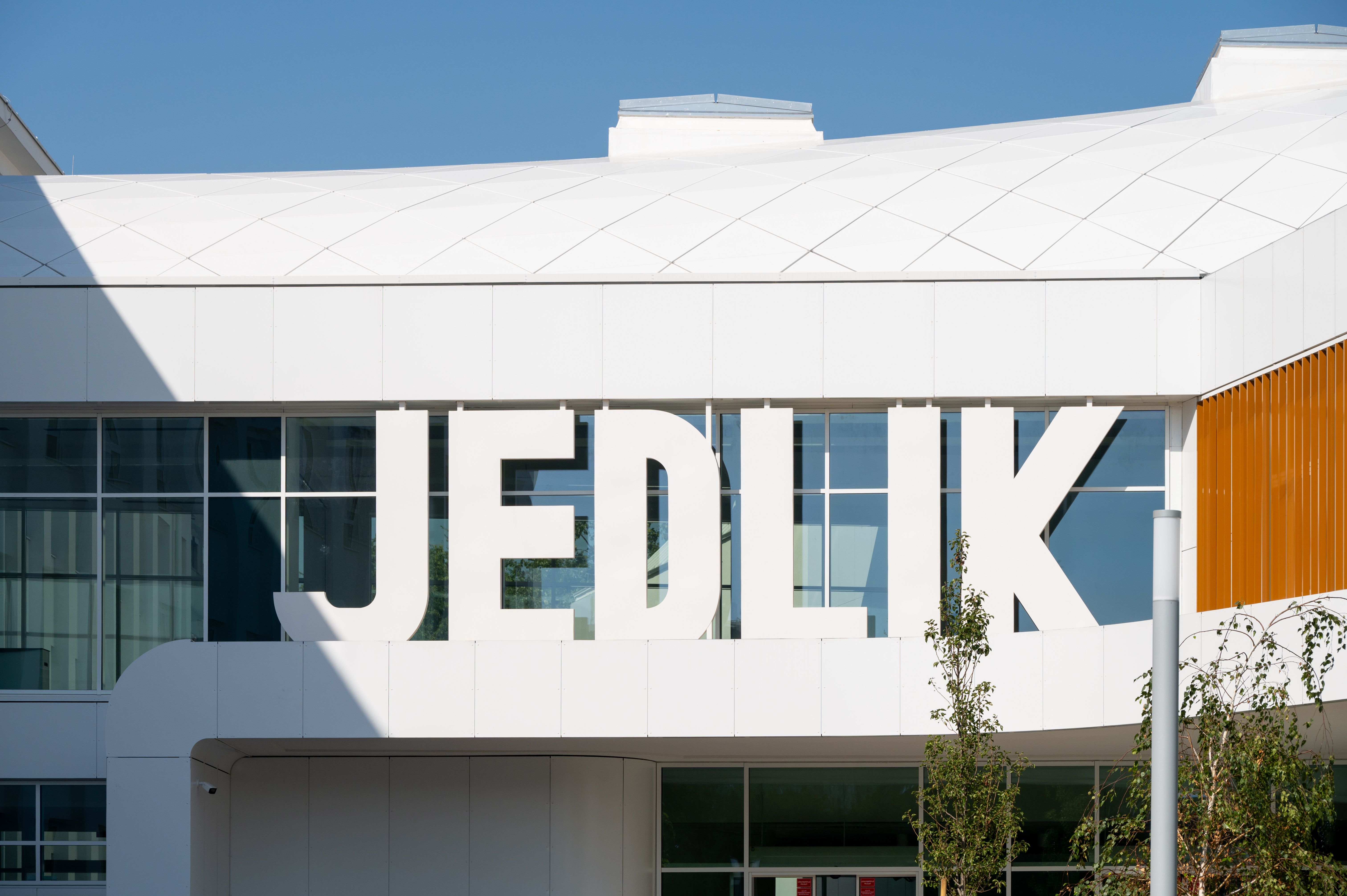
One of the awards came from the 2024 Tekla BIM Awards competition, where the project was selected as a winner not only by the professional jury but also through public voting, standing out in an exceptionally strong field. Another award came all the way from Ljubljana. The BIG SEE Awards for architecture and interior design were presented at the BIG Architecture Ljubljana Festival, where renowned experts and enthusiasts from all over the world gathered to celebrate innovation in the industry. This time, the bim.GROUP team also had reason to celebrate, as we achieved a podium position in the “Education” category and qualified for the grand final—although, unfortunately, a different project ultimately won there. The competition featured outstanding submissions, evaluated by a 14-member internationally recognized jury. The success did not stop there: the trophy cabinet continued to grow, as in the same year the building also received the Construction Industry Excellence Award in the public building/education category, which was ceremonially installed on the building itself.
WITH THE ADVANTAGE OF PARAMETRIC DESIGN
During the design of the Jedlik Ányos Gymnasium, we applied a different, widely used methodology. With the help of parametric–algorithmic design, the entire fabrication design model can be built relatively easily and in a controlled manner, adapting to any geometry. In such a process, the results of prototype manufacturing and trial assembly can be integrated relatively easily, which ultimately reduces both lead times and costs.
“With algorithmic design, we can ensure that no further errors are accumulated in the structure, as every operation is mathematically perfectly precise. Because of this, no significant on-site problems or difficulties occurred anymore,” said Arnold Gyuricza, project-leading structural engineer. “I would add,” said Ádám Szabó, lead architectural designer and general project manager.
With algorithmic design, we can ensure that no further errors are accumulated in the structure, as every operation is mathematically perfectly precise. Because of this, no significant on-site problems or difficulties occurred anymore.
Arnold Gyuriczalead structural engineer.
Several disciplines within bim.GROUP Kft worked on the layered steel structure. In recent years, for our ‘flagship’ projects it has become common practice—or even a necessity—to carry out prototype manufacturing and trial assembly in order to optimise the structural design for production and installation. Achieving the optimum requires coordinated collaboration between design, manufacturing, and construction, where everyone contributes their own technical insights and capabilities. This is already routine for us, and as a result, jointly agreed schematic solutions can be further refined and optimised through prototype manufacturing and trial assembly based on certain performance metrics. With just a few appropriately selected standard solutions for the structural system—and with the help of parametric–algorithmic design—the entire fabrication model can be built relatively easily and in a controlled way, adapting to any geometry. Into such a process, the results of prototype manufacturing and trial assembly can be readily integrated, ultimately reducing both lead times and costs.
THE ALGORITHM DOES ITS JOB, PARAMETERS ARE VARIABLE
We work with a parametric–algorithmic design method, so called because one of its key principles is to model structures using parameters that allow the design to be easily recalculated if needed. This method is not only a tool for optimisation but is often necessary due to the complexity of the task itself. Its application significantly accelerates concept design, preliminary design, decision-making preparation, and fabrication modelling, thereby reducing both time and costs. For example, if a client’s requirements change, or supplier specifications differ—such as when glass panels of different geometry become available than originally planned—the entire concept can be quickly and dynamically updated by modifying parameters, with changes automatically propagated through an algorithm. Every change follows logically from the previous one. The next award also came from Ljubljana. The BIG SEE Awards for architecture and interior design were presented at the BIG Architecture Ljubljana Festival, where renowned experts and enthusiasts from all over the world gathered to celebrate innovation in the industry. This time, the bim.GROUP team also had reason to celebrate, as we achieved a podium position in the “Education” category and qualified for the grand final—although, unfortunately, a different project ultimately won. The competition featured outstanding submissions, evaluated by a 14-member internationally recognized jury. The success did not stop there: the trophy cabinet continued to grow, as in the same year the building also received the Construction Industry Excellence Award in the public building/education category, which was ceremonially installed on the building itself.
Allow cookies to view this content
For a non-expert, this can be translated as follows: if any participant in the project decides that something needs to be changed, the entire system can be updated with a single click—the model quickly tracks and generates all necessary modifications automatically. Writing the underlying program code is a longer process, but this higher initial time investment results in later returns across all areas. Although producing the designs is a time-consuming phase, this work pays off in the long run.
As the use of this design culture became established at the company about ten years ago, we acquired the necessary engineering knowledge over time. Given the complexity of today’s design tasks, this approach and toolkit are essential. For example, in the Jedlik Ányos Gymnasium project, a freeform structure like this would have been extremely difficult—or in some cases impossible—to design using traditional manual methods.
Ádám Szabólead architectural designer and general project manager
THE PLAY OF LIGHT
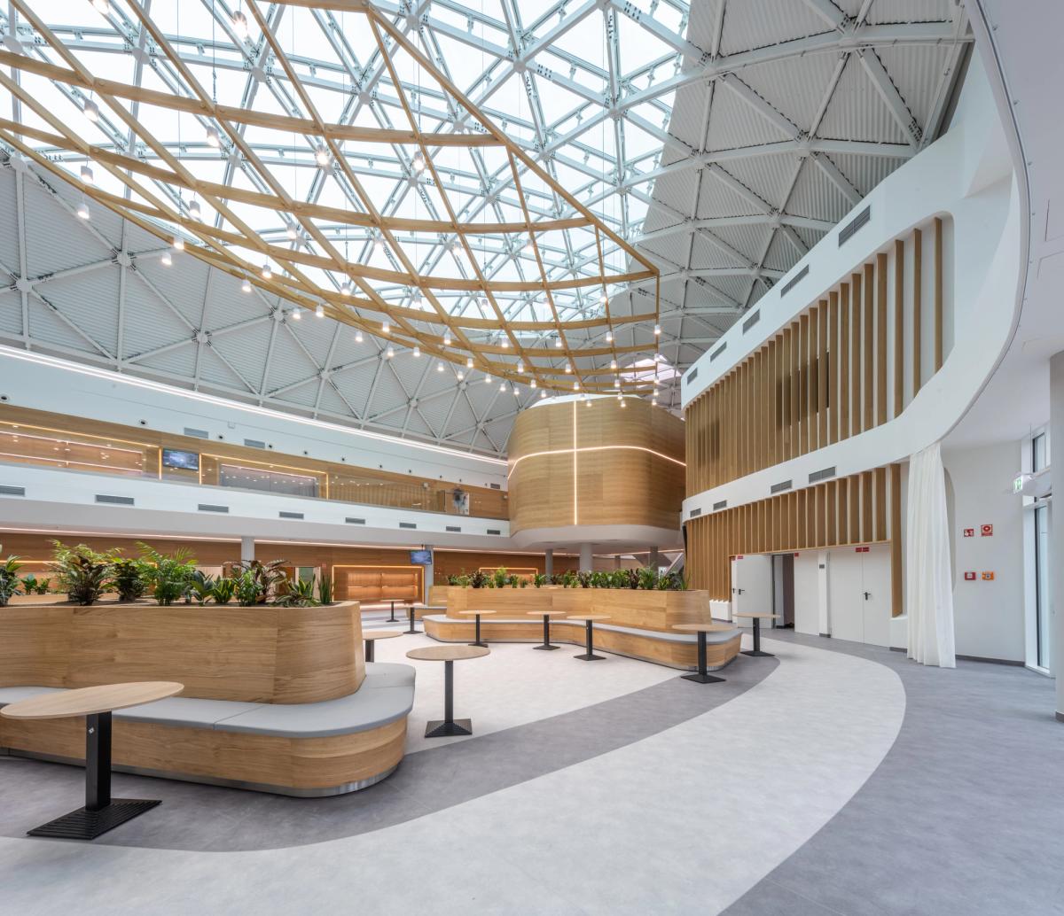
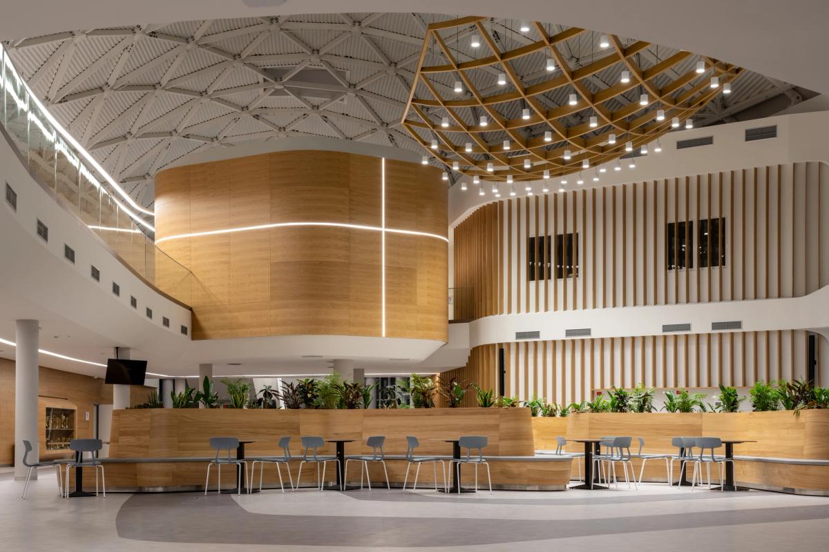
The old building was not only expanded with a similarly minded modern wing, but also enriched with a highly aesthetic and functional architectural element: a roof structure that brings in natural light with engineering precision. During its design, special emphasis was placed on natural lighting and the use of daylight throughout different times of the day. In developing the concept for the atrium and the glass roof, we also had to examine what mandatory school events take place there. Whether it is the start or end of the school year, graduation ceremonies, or national holidays—these are all times when large groups of people gather on site. For each of these dates, we had to track how the sun moves and which surfaces of the glass roof would be most exposed to heat gain. We also had to determine how to size the layers of the glass structure to reduce thermal load. Our goal was to ensure that even with large crowds, the temperature remains comfortable, and no hotspots develop where concentrated heat from the glass could potentially cause discomfort or even fainting. Regarding the design of the atrium, it can be said that we designed a massive structural system—84 meters long and 25 meters wide—covering an elongated atrium space. A Zambelli RIB-ROOF metal roofing system with rainscreen cladding was installed on the steel framework visible from below, and a glass dome is also located in the center. The steel structure is supported by two perimeter reinforced concrete edge beams, curved both in plan and elevation. The geometry of the steel framework was aligned with the layout of these edge beams.
STRUCTURAL CHALLENGE
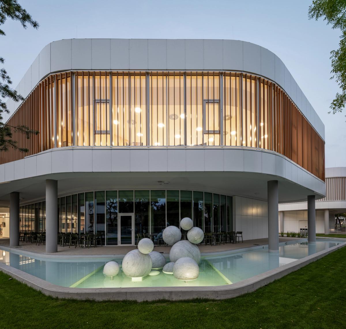
In addition to its educational function, the building also serves a representative role; therefore, when selecting structural solutions, special attention was paid to ensuring that they support architectural and aesthetic goals to the greatest possible extent. The work consisted of two main parts: the transformation and renovation of the existing educational wing, and the design of the new building wing. The newly planned structure was constructed directly next to—but separated from—the remaining and renovated building, on the site of the demolished gymnasium wing. The new extension fundamentally serves three functions: (1) educational spaces; (2) an atrium; (3) a sports hall.
The roof functions as the building’s “fifth façade,” which is also of outstanding architectural significance. The roof structure is 84 meters long and 25 meters wide, covering an elongated atrium space. The steel structure is supported by two monolithic reinforced concrete perimeter beams, typically with a cross-section of 50×75 cm, curved both in plan and elevation, with locally varying increased dimensions. The execution of these complex cast-in-place concrete elements represented an exceptionally high level of construction quality throughout the building, which was essential for the proper formation and anchoring of the roof structure.
These beams also function as the upper edges of the floor slabs of the educational wings adjoining the atrium and the gymnasium. Their extensions beyond the floor slabs are supported by circular cross-section monolithic reinforced concrete columns, one or two storeys in height. The two linear supports of the roof structure are connected by a monolithic reinforced concrete “coffin slab” at the fire compartment boundary, as well as an additional curved monolithic reinforced concrete beam. The horizontal components of the membrane forces were resisted by the floor slab diaphragms, for which the perimeter beams were stiffened with ribs.
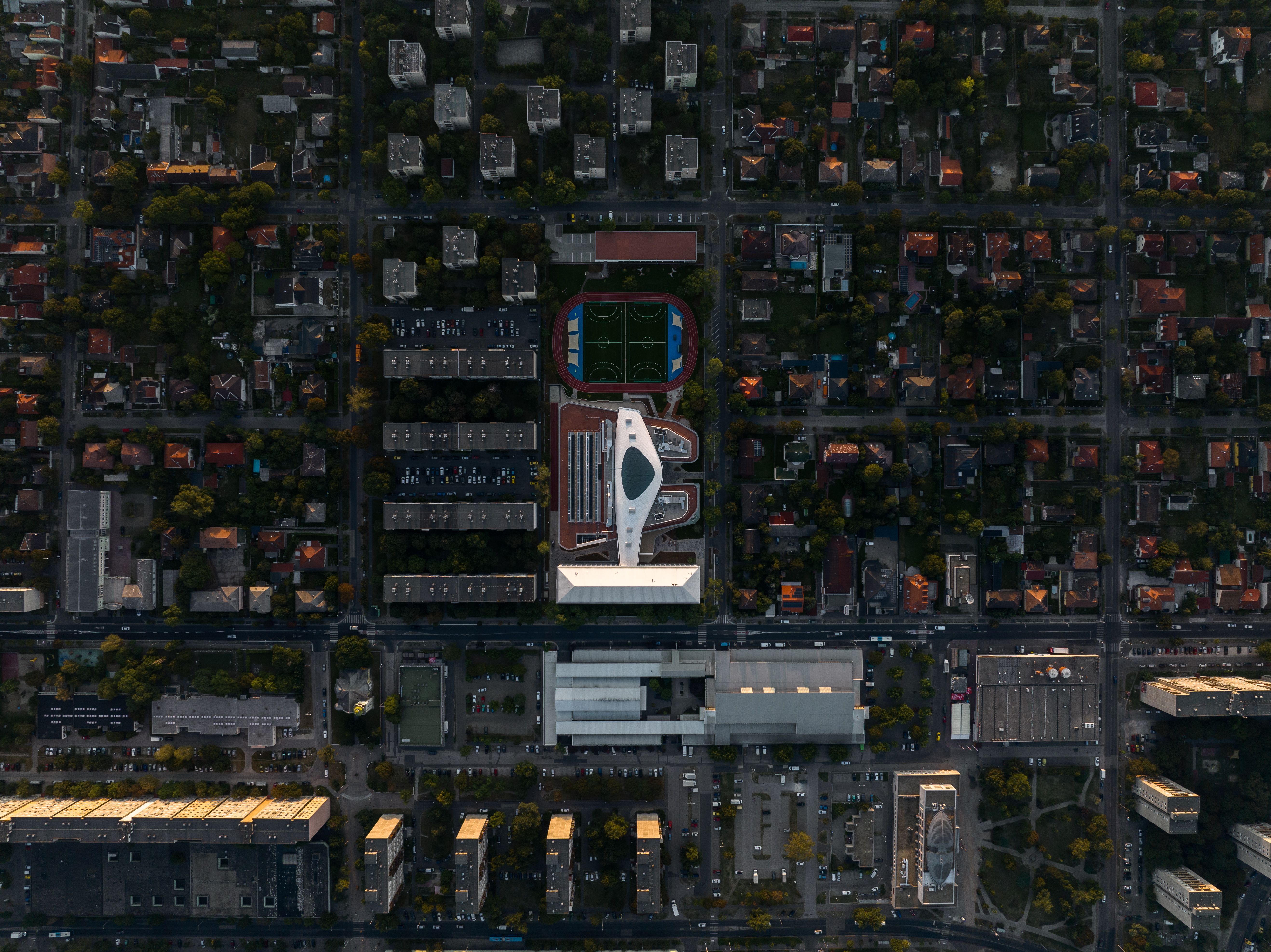
The alignment of the perimeter beams followed the doubly curved contemporary architectural surface conceived during the concept design phase. Based on the boundary conditions (complex geometry, cladding attachment requirements, exposed steel structure, etc.), topological iteration and preliminary structural analysis were carried out using parametric–algorithmic methods, with active collaboration between the architect and the structural fabricator. As the final structural system, two-hinged arches working in compression and bending (hereafter: main girders) were developed in the transverse direction of the roof.
For triangulation purposes (important because it allows flat cladding elements to be installed despite the complex geometry), the arches were approximated with segmented straight elements. This was made possible by an early rationalisation of the surface: the irregular, continuously varying-radius curves were converted into two regular circular arcs. The straight segments were welded in the factory, enabling assembly without temporary shoring and allowing easier lifting into place. Spatial stability was ensured by intermediate hinged, bolted rods (cross members), which braced the main girders at key points and formed the final spatial frame. The centreline of the main girders—following the surface geometry—extends above the reinforced concrete perimeter beams; therefore, their end points are connected to embedded steel components fixed into the concrete. The horizontal components of the membrane forces were resisted by the ribbed beams, which eliminated the need for visually undesirable—and structurally necessary—tie rods. The most characteristic node of the roof is the intersection of the main girder kinks and the connecting cross members. To avoid weld congestion, a CHS element was placed at the centre of the joint. Both RHS main girder membersand the four RHS cross members connect to this via fillet welds, with knife plates forming the bolted double-shear connections using through-threaded rods. To eliminate manufacturing and assembly inaccuracies, the entire roof was divided into a few larger prefabricated and assembled units. Typically, the roof was segmented into units containing 4–5 main girders, between which bolted connections with slotted holes were designed for the on-site assembly phase, and later tightened to the specified torque in the final state.
It is also worth mentioning the transformation of the existing building, which was a high-quality renovation task. A new lift was installed, and at the original entrance on the Táncsics Mihály side, a plant atrium was created by partially removing several floor slabs and opening up the space vertically. In this area, the transverse reinforced concrete main beams were preserved, while reinforced concrete slabs, brick vaults, and longitudinal secondary beams were cut using manual, non-destructive methods. The lift installation followed a top-down construction sequence under strict safety requirements. The floor slab removed adjacent to the lift was replaced with a monolithic reinforced concrete flat slab, connected to the existing beams using drilled and bonded reinforcement dowels. At basement level, a lift pit was constructed directly adjacent to the existing foundations, requiring the lowering of the masonry foundation planes. This was achieved using staged concrete casting with earth-moist consistency.
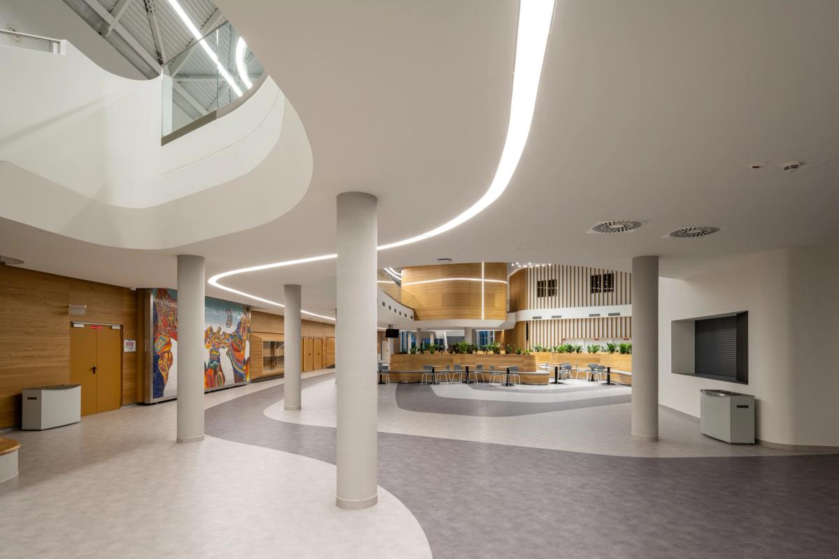
MAIN STRUCTURAL ELEMENTS OF THE NEW BUILDING WING – LECTURE HALL AND ENTRANCE/CANTEEN MONOLITHIC REINFORCED CONCRETE ROOF SLABS
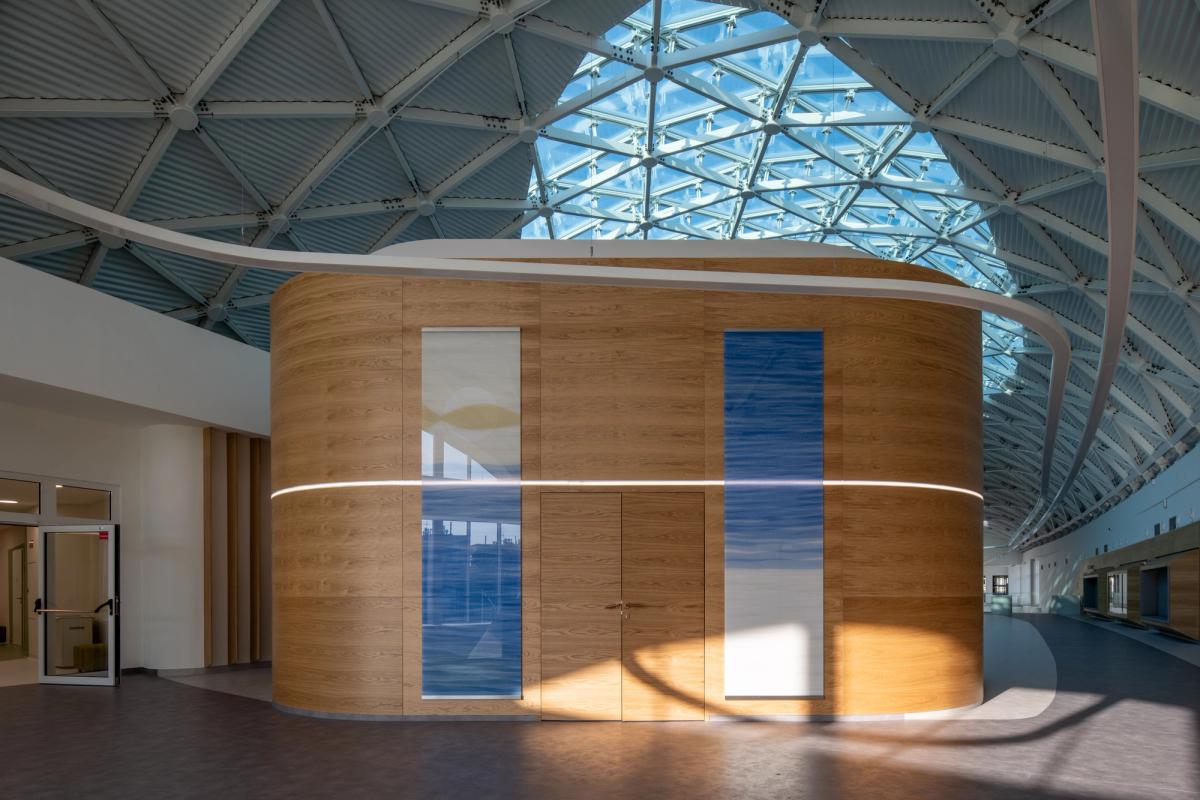
The lecture hall roof slab is designed as a 60 cm thick coffered slab (U-Boot® system). The U-Boot concrete system is a structure lightened with plastic “cassette” elements, allowing the optimisation of structural self-weight and stiffness depending on the cassette type and slab thickness. This solution was applied where architectural requirements specifically demanded it, namely: (1) in the lecture hall, where a span of more than 15 metres had to be bridged with a flat slab without intermediate supports; and (2) at the entrance canopy, where a cantilevered structure was required (an alternative steel truss system was also designed, but ultimately the monolithic reinforced concrete slab was chosen for constructional and aesthetic reasons).
For the structures built using the U-Boot system, detailed layout drawings of the elements were prepared as part of the formwork design, along with key technological specifications, including: (1) precise concreting sequences to prevent flotation of the elements; (2) specified oil-rod testing for accurate measurement of concrete cover thickness; and (3) required strength testing of the first concreting phase. Under the chapel, a mushroom slab with variable cross-section was designed. The chapel space is supported by a single point support (Ø60 monolithic reinforced concrete column). At this point, the slab thickness is 60 cm, gradually decreasing radially in all directions and connecting to the monolithic reinforced concrete gallery slab at a thickness of 30 cm.
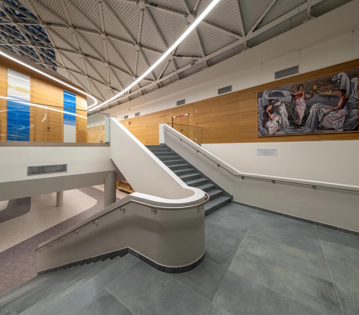
MAIN STRUCTURAL ELEMENTS OF THE NEW BUILDING WING – ATRIUM MONOLITHIC REINFORCED CONCRETE SLAB AND STAIRS
The atrium space is the central and architecturally prominent element of the new building wing, functioning as both an event space and a community area. Longitudinally, it connects to the existing building and outdoor sports fields, while laterally it is enclosed by the educational wings and the sports hall. It includes an intermediate gallery level, accessible from the ground floor via two monolithic reinforced concrete staircases.
The staircase at the eastern end of the atrium, facing the sports fields, is a turning stair with an intermediate landing width of approximately 3 metres. It has no intermediate supports; only the ends of the two stair flights are connected to the foundation and to slabs/columns. The main load-bearing elements of this staircase are the edge upstand beams. Due to its geometry, significant horizontal forces occur at the supports, which are resisted by reinforcement anchored into the slab above and by a substantial base beam system below. The staircase was also checked for vibrations induced by pedestrian movement (so-called “footfall analysis”).
The straight staircase consists of two intermediate landings. It is supported at the bottom on the foundation and at the top by connection to the slab and column. Its primary load-bearing elements are the railings, designed as monolithic reinforced concrete upstand beams.
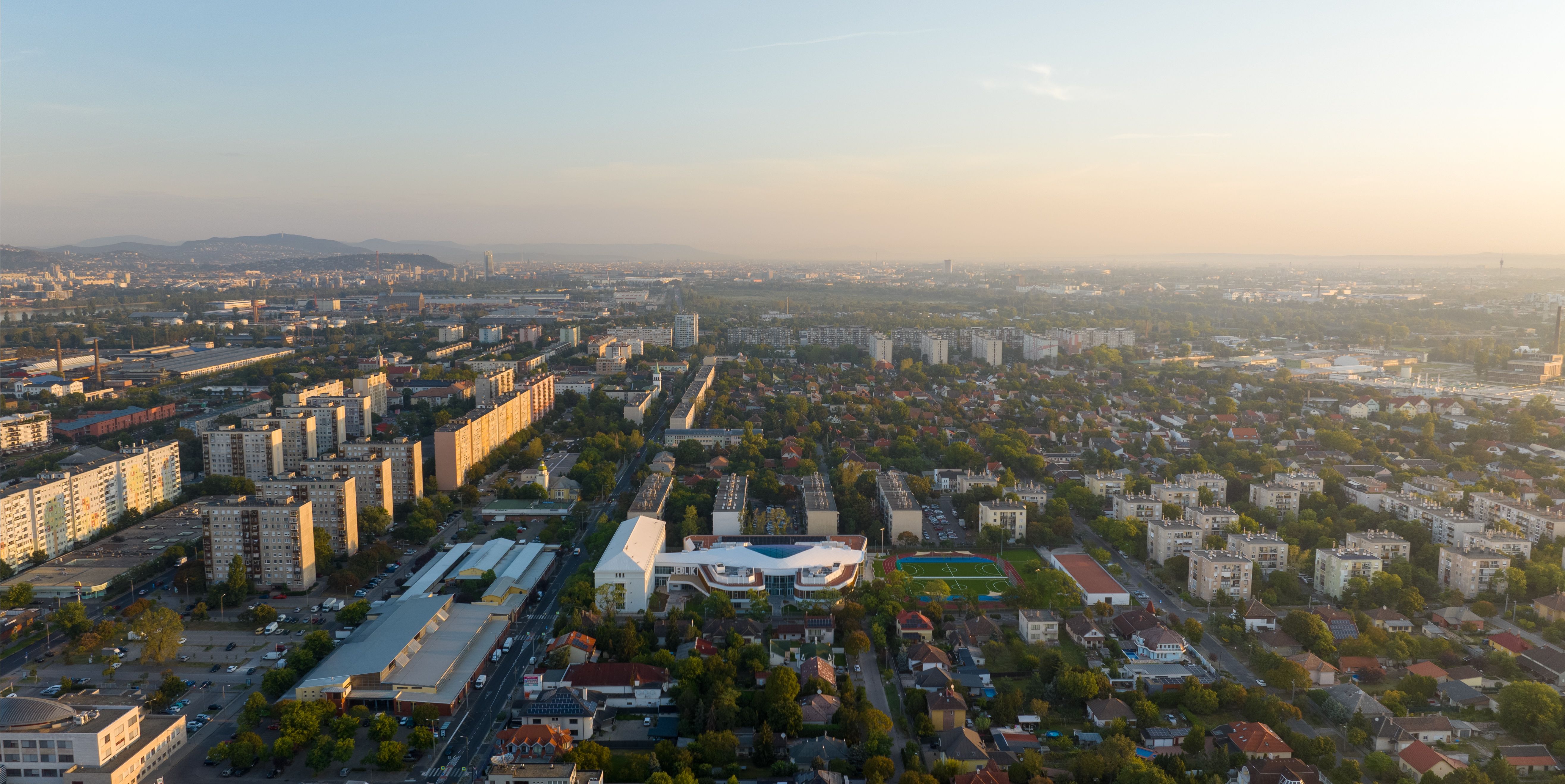
OUR PARTNERS WERE ESSENTIAL TO THE REALISATION OF THE PROJECT
The design was prepared with the involvement of key stakeholders playing an important role in the life of Csepel and the school. From the very beginning, a committee was formed to discuss and define requirements. From our perspective, this was a highly beneficial approach, as it supported the design process and significantly reduced design time, since the client had already defined all expectations in advance.
First, a concept design was prepared. This was not created by us, nor did we participate in its competition phase; it was prepared by Zoltán Reznicsek and his team of young architects. Subsequently, the municipality issued a call for further design development—again in a tender form. bim.GROUP Kft (then operating as BIM Design Kft.) won the tender: in the first phase, we prepared the permit design documentation, followed by the tender design documentation. A short pause followed in the process while the construction tender took place, after which the project was realised using a design-and-build delivery method.
Such high-quality work would not have been possible without our partnerships during the project, including the main contractor Laterex Kft., as well as our strategic partner, the companies of the KÉSZ Group (KÉSZ Metaltech Kft., KÉSZ Ipari Gyártó Kft., dvb Kft., Baumetall Design Kft.).
Both in terms of professionalism and attitude, we experienced the collaboration with the companies involved in implementation very positively, and we would like to take this opportunity to thank them. We would especially like to highlight the professionals from KÉSZ, whose manufacturing and installation expertise greatly contributed to the final technical solutions. In closing, on behalf of all bim.GROUP Kft. employees, we are very proud of the realised result.
Gyuricza Arnoldlead structural engineer